1. For Fibre to work the Tx from one end must be wired through to the Rx on the opposing end.
The Tx contains the transmission laser, while the Rx end contains the receiving sensor. If you wire Tx to Tx it will not damage the unit, but will not work. Please note most patch cables are wired through as cross-over (ie A-B and B-A). Check the wire numbers on the patch cables.
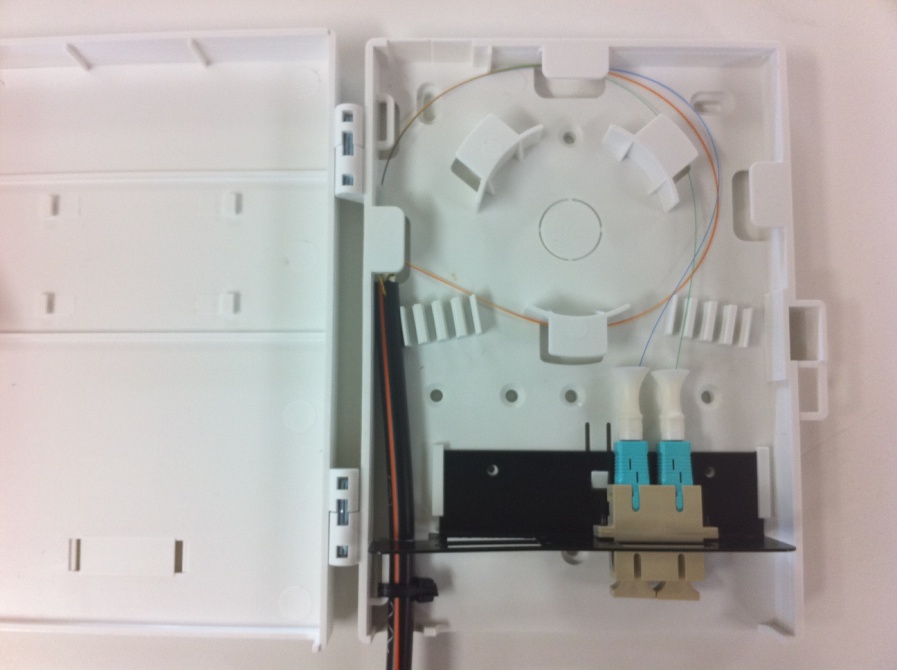
2. Insert a SC connector coupler into the black flame located in the bottom of the box.
The black frame can be removed using the plastic release. Use the screws provided to secure the SC connector coupler.
3. Once you have terminated all your fibre connections (you only need two: Tx and Rx), you are ready to install this into the fibre termination box.
Below is an example of how we have done this. We have passed in the fibre cable on the left hand side and used a cable tie to mount the cable sheath to the plastic box for strain relief. This will stop someone pulling on the external cable and risking damaging the internal terminations.
4. Guide the cores around the centre circle of the termination box.
The purpose of this is to stop the cores being bent tighter than their minimum bending radius.
5. Plug the SC connectors into the SC connector coupler.
6. Plug a fibre patch cable from the SC connector coupler to your end device (for example a Fibre Ethernet Switch).
For the next stage go to part 4 of the tutorial... Fibre Termination Part 4 - DIstribution Box Setup
For more information on the products used in this tutorial, please see the ECS Fibre Networking PDF